Steps For Building The Jeffrika7b
- Get your Mise en place.
- Glue the Conduit Straps onto the PVC pole.
- Cut the top and bottom VHF sections of the antenna.
- Straighten the wire.
- Bend the VHF sections.
- Bend the UHF sections.
- Make the clamping brackets.
- Make the standoffs.
- Mount the Elements.
- Install the Standoffs.
- Add the Balun
Collect all of the raw materials from the list above, and gather your tools. Maybe clean off your bench a little bit. Open up a copy of the the measurements and put them someplace easy to read. There'll be some pictures to follow, but for sizes and lengths, always refer back to the measurement sheet.
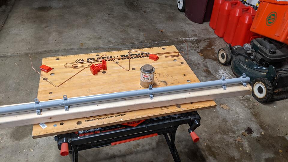
The PVC glue needs a few hours to dry, so do this step early. Mark the pole
with the location of the five PVC conduit straps. I left about 3/4" of pole
left at the top, in case I ever wanted to mount another pole section onto the
antenna with a PVC coupler. It is fairly important that you get the brackets
glued on nice and flat with respect to each other. Note that you can't just
put the pole on the bench and glue the straps facing down on the bench! The
straps are actually a little deeper than the width of the conduit, and won't
touch the back of the pole if you do that. Glue it up as shown in the picture,
with the pole resting on top of the straps, and you won't have a problem.
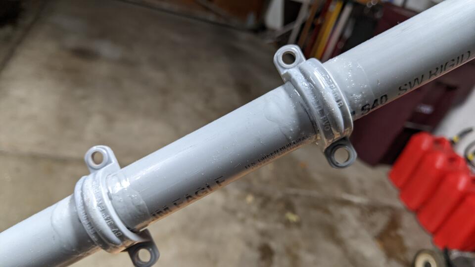
Use lots of glue, and rock the straps and pipe together to ensure a strong plastic weld. There is nothing else holding the elements onto the pole, so don't be stingy with the adhesive! Let the welds dry for a few hours before trying any final assembly.
The VHF sections, or top and bottom NARODS, are the easiest to build, and the
shortest wire elements in the antenna. They are good place to start with your
wire measuring, cutting, straightening, and bending techniques. If you screw
it up while learning, you won't have wasted much of your wire.
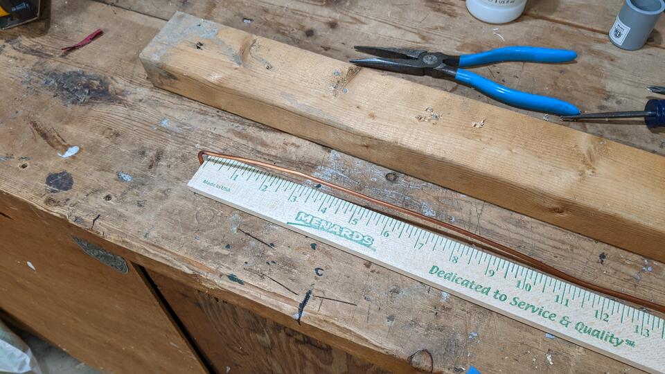
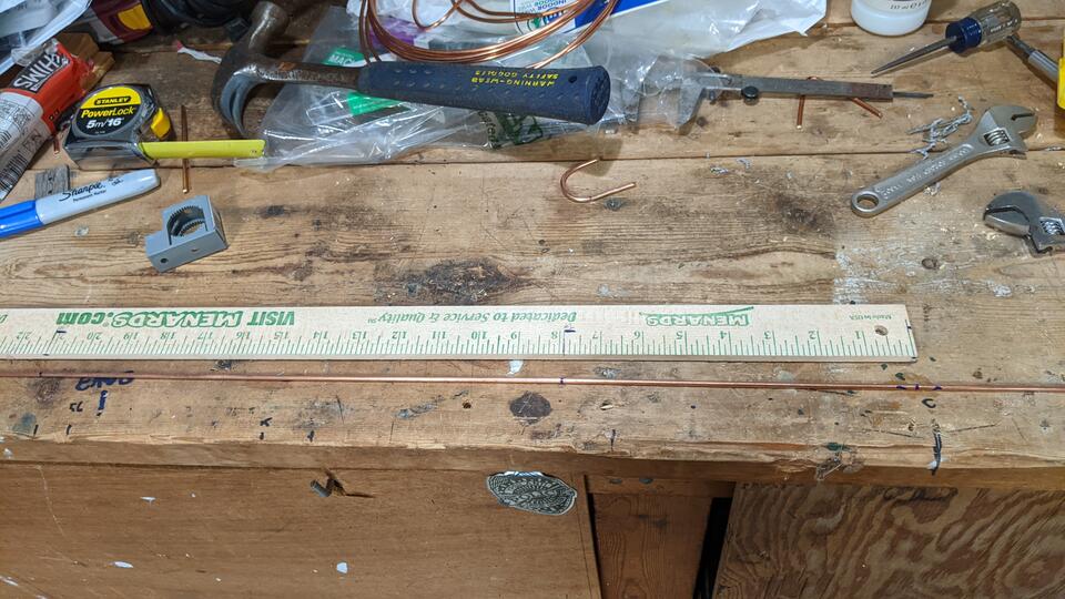
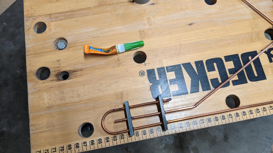
A wooden yardstick (or meter stick or centi-femtoparsec stick) comes in very
handy here. Take your measurements for the wire segment bend points and write
them directly on the stick. Then put a short ~3/4" 90 degree bend in one end
of the wire. Hook that over the stick, then unroll the amount of wire you need
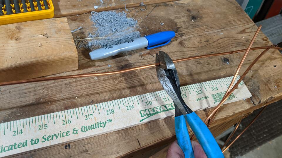
plus like 2" of extra wire and cut it off of the roll. You can always
make a length of wire shorter later, but you can't easily make it
longer, and you are probably going to lose some overall length due to
bend radii. Therefore, it pays to remember that old adage, "Measure thrice, cut
twice" when bending wire.
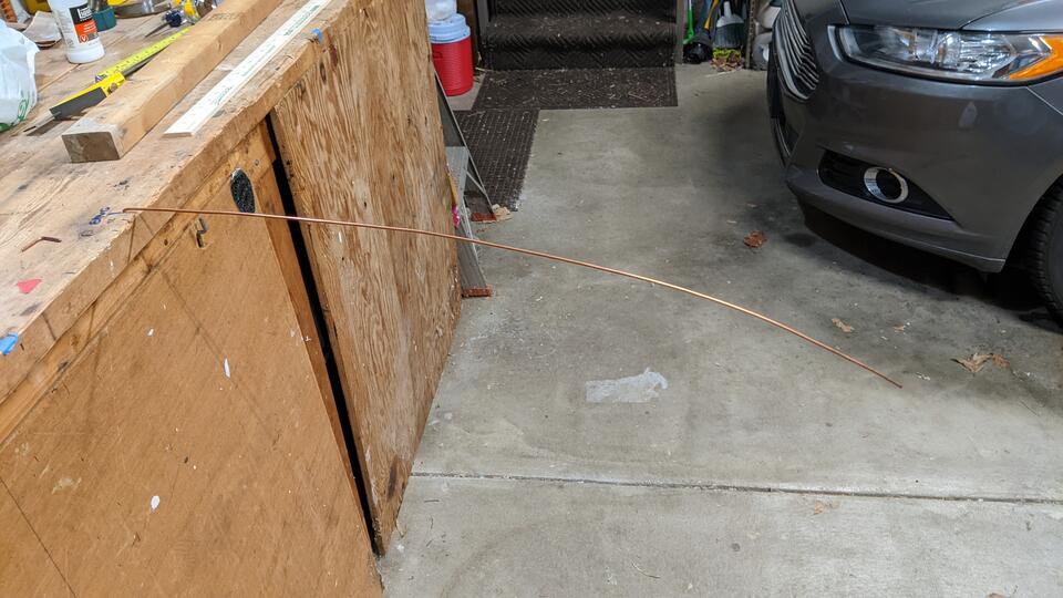
The #8 AWG wire is pretty tough to bend with just your hands, so getting it
straight is difficult without a good technique. Luckily, one exists. Start by
drilling a 9/64" inch hole into the top of your workbench, then put the little
90 degree bend that you put in the wire into the hole. (Or, I suppose, grab
that little bend with a bench vise, or put a hole in to a block of wood and
clamp that to your bench. How you treat your work surface is up to you.)
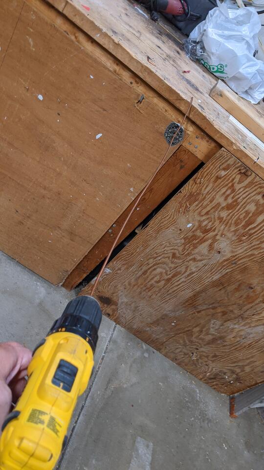
Put the other end of the wire into the drill motor, then, while pulling a little bit on the wire, slowly turn the drill a few turns clockwise to start. Then twist the wire twice as many turns counter-clockwise and twice as many turns clockwise, repeating that until the wire is dead straight. Finish off with the same number of counter clockwise turns as you started with, and like magic, the wire will stay straight until you are ready to bend it again.
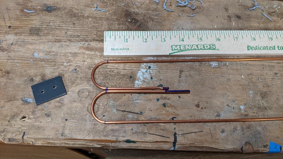
Find the center of the VHF element wire, mark it with the sharpie marker, and use the yardstick to mark where you are going to make your bends in the wire. A small piece of PVC conduit works great as a bending form for the two half-loops that you need to make in each element. So would a dowel, or a broom stick. You'll probably be able to bend this wire around the form by hand, like I did, or you could use some pliers. If you did it right, you'll have some slop wire left at the ends to trim off later. Don't worry if your radius bend isn't 100% perfect here. Just get the parallel sections to be the correct lengths and distance apart, and it'll be OK.
Mark up the other side of your yardstick with the correct lengths and bends for
the UHF sections, then cut and prepare two lengths of wire, like you did with
the VHF elements. Remember to put the little hook into one end of each
element, leave at least 2" of slop in the overall wire length, and
straighten the elements with the drill motor trick.
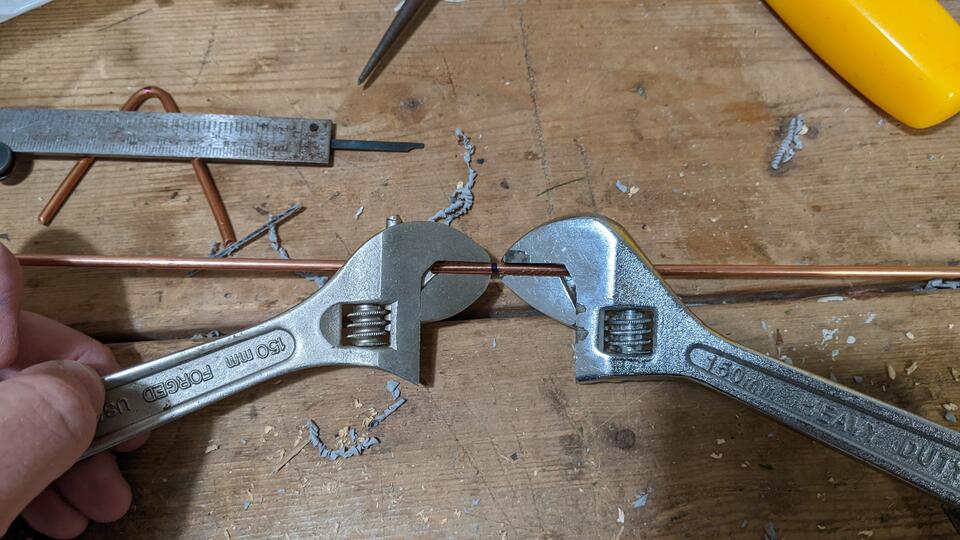
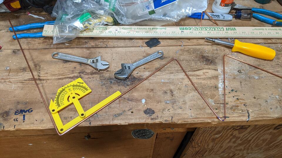
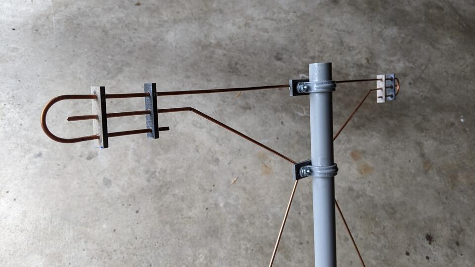
Mark the center of the wire, and start your bending process from that mark. That is the bend where the feedpoint will connect, at the middle conduit strap. Bend from the center out toward the ends of the wire, so that the extra slop left in the wire will end up at the two ends, where it can be trimmed later. I used a pair of small adjustable wrenches to put the bends into my wires, but a pair of linesman pliers, or a peg jig should work just fine too. Check your work using the angle finder (and the bend angles that I conveniently put on the plans!) and a measuring tape as you go.
Across the face of each of the conduit straps, we're going to install a
rectangle of non-metalic plastic material that will serve as a little bit of
extra structural support for mounting our antenna elements. I thought about
simply leaving these out of the design and clamping directly to the conduit
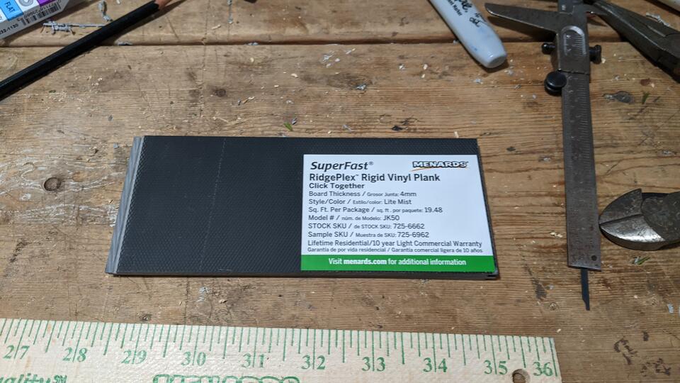
straps, but decided against it. I chose a 'free sample' of rigid vinyl
flooring material for the job, and I'm really impressed with it. It is easy to
cut and drill the stuff, and the wood grain does look kind of cool in the
build. I might even use it for flooring someday! If you feel strange about
snagging a tiny little sample of this stuff for the project, or if the free
sample pool has dried up, you can either buy a box of it or something similar,
or you can cut up regular grey PVC electrical box cover plates from the
electrical department.
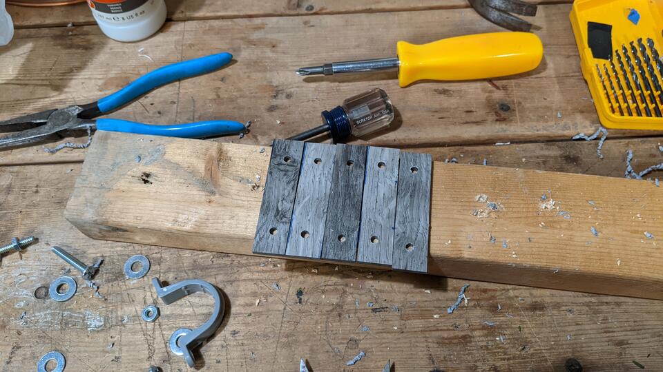
Measure and cut out five strips of bracket material from the sample piece, and drill the two mounting holes in each. I cut these using a cheap plastic miter box and back saw, no power saw required. I drilled the two holes into one of the rectangles by hand with the drill motor (as opposed to on a drill press), checked that they lined up with the conduit strap, then used that piece to line up the drill locations on the other brackets, drilling them two at a time until I had all five pieces drilled. They came out looking square enough.
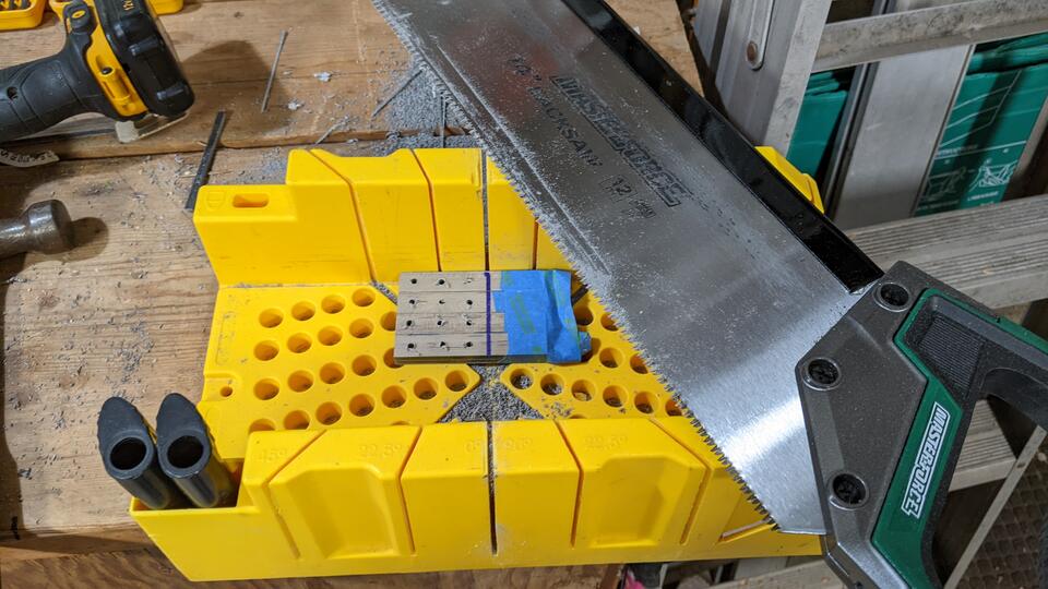
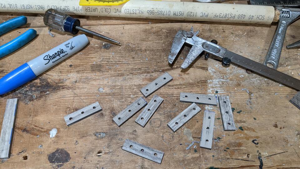
Measure and cut out eight strips of the flooring material, and drill three
9/64" holes in each one. These will be the standoffs that keep the UHF
sections of the antenna from grounding out against the VHF sections. Use the
same method as for the clamping brackets to speed up the production. Make
yourself a template, then use it as a drill and cut guide, and make them in
parallel. In the picture, you can see I'm about to trim eight of them all at
once!
These standoffs are pretty important, structurally. The top VHF element is susceptible to bird landings, and the weight of a good sized bird landing on the end of an unsupported 8 AWG wire could bend it. If the VHF and UHF sections touch, you'll lose both bands. The two standoffs per corner, once superglued in place, will add a lot of stiffness and support to the VHF elements, keeping them the correct distance apart to be inductively coupled. Don't skip installing the standoffs!
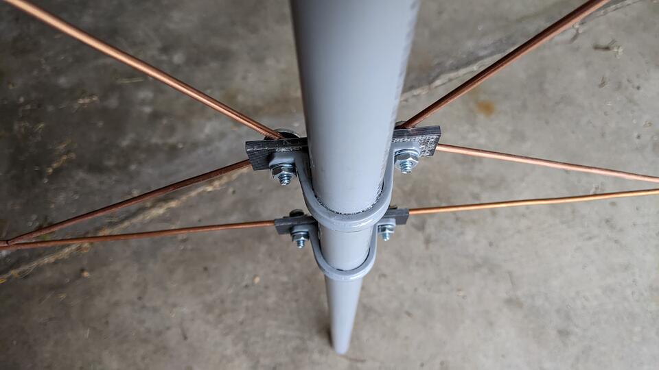
Once the four wire elements are cut and bent, and after the conduit strap glue has dried, its time for assembly. The NEC model of the antenna uses 1" bolts all around, but simulation tests showed that shorter bolts always perform marginally better. For construction, I kept the 1" machine screws for the feed support bracket, but was able to change to shorter 3/4" machine screws for the four non-feed support brackets.
The 1/4" washers do a better job of clamping down on the wire elements if they are bent into the wire by about 30 degrees, so use the pliers or wrenches to put a slight bend into the ten 1/4" washers.
The stacking order for the non-feed supports is: 3/4" Machine Screw, 1/4" Washer,
Copper Wire Element, Clamping Bracket, Conduit Strap, Small Washer, Nut.
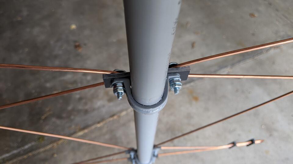
The stacking order for the feed support bracket is slightly different, because there needs to be a convenient place to mount the balun feed without having to loosen the center support of the UHF element. The order for the center feed support is: 1" Machine Screw,1/4" Washer, Copper Wire Element, Clamping Bracket, Conduit Strap, Small Washer, Nut, (Balun Blade Connector), Small Washer, Nut. Tighten down the first nut in the stack, but leave the second one loose for now, to clamp the balun transformer later.
Install the eight standoffs between the ends of the VHF and UHF elements. This is a task that is easier said than done, and it might make for a good stand-alone brain teaser puzzle that you could make with some left over wire and extra standoff pieces. You'll see what I mean when you try to install them.
The method I used was to slide the inside standoff over the end of the VHF
element, around the bend, then over the end of the UHF element through the
center hole, sliding it all the way over to the bend in the UHF element. Do
the same with the outside standoff, then slide the outside standoff over the
end of the VHF element through the final hole. Do the same with the inside
standoff. Slide both standoffs into the correct place, and repeat for the
other ends of the antenna.
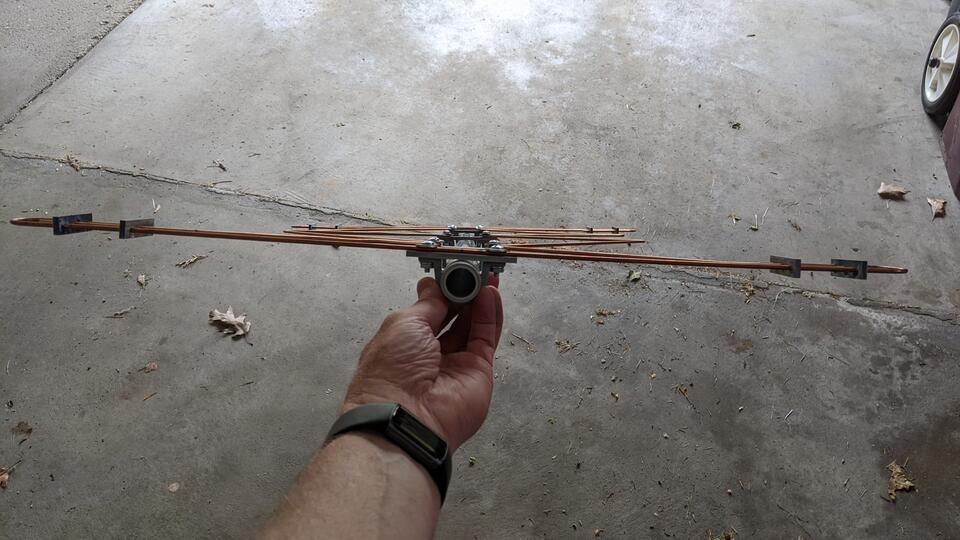
Once the standoffs are in place, make your final adjustments to the angles and placement of the elements. The VHF element may want to 'twist' around the UHF element, so when you go to glue in the supports, you'll need to keep the standoffs flat. Lay the antenna on its face, apply the glue to the wire elements and standoff holes, and then put a weight like a small two-by-four on top to hold them down while the glue dries. The superglue gel from the parts list has a lot of body and maybe thirty seconds of 'working time', so keep the joints still for a few minutes before moving on to the next set.
Do a final check of your wire end measurements, and trim off any remaining slop in the wires to get them to the correct lengths.
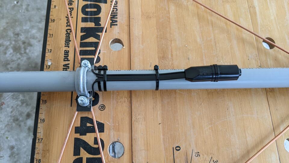
Its the last step before mounting! Attach the two leads from the balun transformer to the center feed taps, and tighten down the nuts. Use a few zip ties to secure the transformer to the pole. Note that the transformer has a weatherproof boot, and that should be pointing down toward the bottom of the antenna.
If you want to pre-mount the amplifier on the antenna pole, this is a good
time to do it. Run a 3ft section of coax from the transformer down to the
antenna side of the amplifier, and secure the amp fairly low on the pole using
the mounting hardware that came with it.
Check the antenna one more time for squareness and flatness, make any minor
adjustments, and that's it! You're ready for whatever mounting adventures
await you.